Techniques to Measure Airflow Velocity
How to accurately monitor and measure airflow in mines.
Common Techniques to Measure Airflow
As with any industrial application, safety is key. Safe working environments for workers, for employers, and for the general public is critical. This is no exception in mining. One major concern for safety in mining is proper ventilation in the mine. Improper ventilation techniques can lead to reduced air quality underground, reduced oxygen levels, and even a build up of toxic gases. This is why it is vital to monitor and measure airflow in mine shafts, to properly control ventilation systems. Below, some common techniques for monitoring and measuring airflow are briefly explained.
Rotating Vane Anemometer
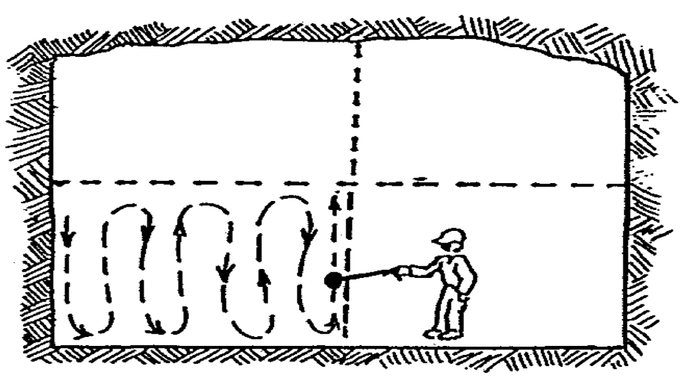
A rotating vane anemometer measures airflow through mechanical velocity. Airflow passes over the propeller of the vane anemometer, causing rotational motion. The speed of rotation is then converted into a value for airflow speed. Vane anemometers can typically measure airflows in a range of 1 m/s to 15 m/s. Speeds below this range are too low to obtain accurate readings, and depending on the device, speeds above this range may be damaging. Like any fluid flow, airflow is subjected to skin friction. Airflow through a duct of tunnel is not uniform, especially if the tunnel is not perfectly smooth. To obtain a value for average airflow in the duct or tunnel, the anemometer must transverse the cross section of the area in question. This way, multiple readings can be averaged to obtain one value for average airflow through the tunnel.
Velometer Airflow Measure Probe
Another method for measuring airflow speed is by using a velometer. A velometer provides an instant reading of the speed of air at a specific point where the probe is positioned. An average speed can be obtained by measuring multiple spots along the cross-section of the airflow, much like with the anemometer, but this is much more cumbersome. This is commonly used to spot-check specific speeds at fixed points.
Measure Airflow Using Differential Pressure Sensors
Pitot Tube
Aircrafts use pitot tubes to determine airflow velocity, and effectively determine the velocity of the aircraft. This same technology is also employed in industrial applications, such as ducts or tunnels, to determine airflow. A pitot tube works by measuring both stagnant and free-stream static pressure in the airflow. Stagnant pressure is the static pressure of a fluid stream at a point where the velocity is zero, such that all kinetic energy of the flow has been converted to pressure energy. The stagnation pressure of a flow is equal to the free-stream dynamic pressure plus the free-stream static pressure. The free-stream static pressure is easily measured by the pitot tube, and the dynamic pressure can be calculated according to the following formula:
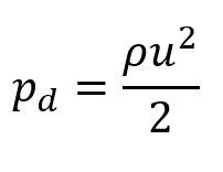
Where pd is the free-stream dynamic pressure, ρ is the fluid density, and u is the flow velocity. As previously mentioned, the stagnation pressure is equal to the static pressure plus the dynamic pressure. Using this, and rearranging the formula for dynamic pressure to isolate for flow velocity, the flow velocity can be determined as a function of stagnation pressure and static pressure, as shown:
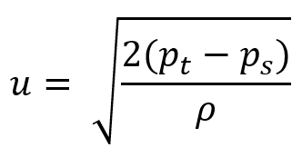
Where pt is the stagnation pressure (total pressure) and ps is the static pressure. This shows that the velocity of the fluid is proportional to the difference between the total pressure and the static pressure. This is the premise of the differential pressure sensor. Much like the velometer, the differential pressure sensor can measure velocity of a fluid at a specific point. Since fluid flow is not uniform, the sensor will either have to transverse the cross section of the area, or multiple sensors will have to be employed, to measure an effective average flow velocity.
Piezoresistive Sensors
A piezoresistive material is a material which changes the resistance of electrical current flow when the material is compressed or strained. A commonly used material for a piezoresistive pressure sensor is the semiconductor silicon. When silicon is compressed, it provides more resistance to electrical current passing though. This relationship between pressure and resistance is mostly linear. Using similar techniques as the pitot tube, a silicon semiconductor can be used to calculate a pressure difference in an airflow stream, and this data can be used to measure airflow velocity.
Ultrasonic Flowmeter
Ultrasonic flow meters measure airflow by using ultrasonic waves. The speed of which a sound wave travels through a medium is known as the speed of sound. Ultrasonic sensors can be arranged to send a signal from one sensor through the cross section of a tunnel or duct and be received by a sensor at the other end. If the two sensors are positioned at an angle to the cross section, then the soundwave will be affected by the airflow. For example, if a signal is sent from a sensor and travels along the direction of airflow to the next sensor, the time for the sensor to receive this signal will be less than if the signal was sent against the direction of airflow. By sending two signals – one with the airflow and one against the airflow – the speed of the airflow can be calculated based on the time difference between the two signals. Since the air temperature remains constant during this measurement process, the time difference will be directly proportional to the air speed.
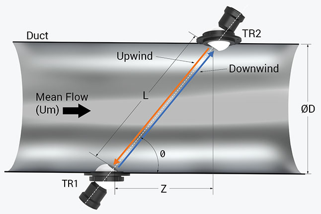
Using this method to measure airflow provides a very accurate reading at virtually any airspeed, even if there is no airflow at all. Since the wave travels across the entire cross section of the measured area, there is no need to transverse the area with an ultrasonic flowmeter. The sensor will provide an accurate reading of the average airflow through the tunnel or duct, and the measuring time is very quick.
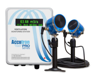
Interested in a simple, accurate method of measuring and monitoring airflow in your mine? Check out our PRO Series Ultrasonic Airflow Monitor.
